Cable faults and troubleshooting techniques
Railway signal cables are important transmission tools for railway signal equipment. The normal transmission of power and signals is related to the normal operation of signal equipment, and plays a pivotal role in ensuring the smooth operation of the railway and the safety of vehicles.

Once a signal problem occurs, the signal equipment will not be able to operate normally.
Signal cables are generally buried underground, and maintenance personnel will not be able to quickly and accurately find the fault point and determine the fault status.
Once a fault occurs, it usually takes a lot of manpower and material resources to dig the cable out of the ground for troubleshooting. This type of troubleshooting method is most likely to cause problems such as low troubleshooting efficiency, long search time, and low test accuracy.
Using existing equipment to minimize the scope of the fault, find the fault point as soon as possible, and solve the fault problem are important issues explored by signal personnel.
This article will combine the work experience in recent years to explore the types of signal cable faults, the main causes, and the methods and techniques for finding cable faults using cable fault testers.
Cable fault types and main causes
Artificial ground excavation and construction factors: During construction, if the direction of the underground signal cable and other laying conditions are not understood in time, and if the underground cable protection measures are not taken, the cable will be damaged due to ground excavation or construction.
Factors of the cable itself: The quality problem of the signal cable itself or the aging of the cable due to long use time, the breakage and leakage of the cable layer, and the damage of the insulation layer are all important causes of cable damage.
Geographical environment factors: Due to the limitations of the geographical environment, the insufficient burial depth of the cable and the leakage of the cable line may cause the signal cable to be damaged during construction or rainy and snowy weather.
Other reasons: damage to the signal cable caused by rodents, insect pests or human theft.
Introduction to cable fault tester
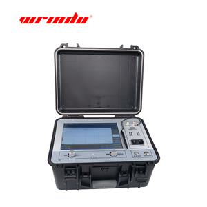
The increasing diversity of cable faults has greatly increased the workload of signal cable maintenance personnel. To find the fault point in a timely and accurate manner, it is essential to use relevant fault detection instruments.
If your company is looking for a cable fault test system, this RDCD-Ⅱ would be a good choice for you. Click RDCD-Ⅱ to learn more about the product.

Contact us for a quote
Cable fault tester is a commonly used cable fault tester, which uses pulse detection. Since each line has a certain impedance, this property is determined by the material and structure of the line. On the transmission line, the input impedance of any point is equal to the characteristic impedance.
If the load connected to the terminal is equal to the characteristic impedance, the current wave or voltage wave sent from the beginning of the line is transmitted along the line and is completely absorbed by the load at the terminal without reflection. However, when the impedance of any point on the line is not equal to the characteristic impedance, the electric wave will produce total or partial reflection at this point.
Methods and techniques for finding cable faults
1. Determine the fault line pair method
Cross-line refers to the insulation penetration fault between the conductors of one or more phases of the cable. When judging cross-line, try to choose a line pair with a small insulation resistance. If there are multiple core wires with poor insulation, test them separately and observe the reflected wave at the same time; if the reflected wave of one group is more obvious during the test and is less affected by the outside world, its test result is used as the basis. A broken line refers to a discontinuous fault of one or more phases of the cable conductor. In the broken line test, the broken line can be tested with any core wire of the same cable. If the reflected waveform affects the starting point judgment, the core wire tested with it can be replaced.
2. Test comparison method
Test and record the fault line, then test and compare the good line with it, and you can determine where the fault point is. Test and record the fault line, then test and compare other fault lines with it, and you can determine whether the fault point is in one place. You can also choose the line with more obvious fault reflection as the fault line for testing, and use its test result as the distance of the fault point.
3. Pair test method
The pair test method is widely used in long cable testing. Due to the unevenness of cable production, when the transmission wave passes through the cable, it will produce large or small reflections. If the fault point is at the far end of the long cable at this time, and the impedance of the fault point is large, the fault waveform may be difficult to identify. If you understand these reflected waves at this time, and then use pair test to confirm, you can determine the fault point.
The specific method is to test the fault at both ends of the cable respectively, and compare the test results at both ends with the full length to determine the accuracy of the fault point. If the test results at both ends do not match the full length, there may be the following two situations: there is a problem in the judgment of the fault point; this cable may have multiple faults.
First, based on the amplitude of the reflected wave, confirm the main fault point, and then solve them one by one. In general, the fault point is found by the test results of the end closer to the fault point in the test. At this time, the following situations will occur:
(1) If the fault reflection fault waves are very clear when testing both ends in the test, the test results of the end closer to the point will prevail.
(2) If there is a fault several meters to more than ten meters away from the starting end (A) at both ends (A, B), and the test waveform at the near end is ignored, the effect of getting half the result with twice the effort will be obtained. At this time, it is easy to identify using the pair test method: If there is a short circuit fault, you can test from the opposite end (B).
Open the circuit at the starting end (A) and observe the waveform changes. If the waveform is downward and there is no change, it means that the fault point is at the starting end (A); then further determine the fault point (at this time, you can also go back to the starting end for testing, check the waveform characteristics of the near end, and then determine the fault point.
In this case, there may be secondary or tertiary reflections, that is, there is a continuous reflection waveform at the near end). If the near end (A) has an open circuit fault, you can test it from the far end (B) and short-circuit the near end (A). If the waveform points upward and there is no major change, it can be confirmed that there is an open circuit fault at the near end. Use the same method as above to confirm the fault point.