Calculation of transformer no-load loss, load loss and impedance voltage
The loss of transformer is divided into iron loss and copper loss. Iron loss is also called no-load loss, which is its fixed loss, which is the loss generated by the iron core (also called iron core loss, and copper loss is also called load loss).
Transformer loss calculation formula
(1) Active loss: ΔP=Po+KT β2 Pk
(2) Reactive loss: ΔQ=Qo+KT β2 Qk
(3) Comprehensive power loss: ΔPz=ΔP+KQΔQ
Qo≈Io%Sn, Qk≈Uk%Sn
Where: Qo——no-load reactive loss (kvar)
Po——no-load loss (kW)
Pk——rated load loss (kW)
Sn——transformer rated capacity (kVA)
Uk%——short-circuit voltage percentage
β——load factor, which is the ratio of load current to rated current.
KT——Load fluctuation loss coefficient
Qk——Rated load leakage power (kvar)
KQ——Reactive economic equivalent (kW/kvar)
The selection conditions of each parameter in the above calculation are:
(1) Take KT = 1.05;
(2) When the system minimum load is taken for the 6kV~10kV step-down transformer of the urban power grid and the industrial enterprise power grid, its reactive equivalent KQ = 0.1kW/kvar;
(3) For the average load factor of the transformer, β = 20% can be taken for agricultural transformers; for industrial enterprises, with a three-shift system, β = 75% can be taken;
(4) Transformer operating hours T = 8760h, maximum load loss hours: t = 5500h;
(5) Transformer no-load loss Po, rated load loss Pk, Io%, and Uk%, see the product factory data.
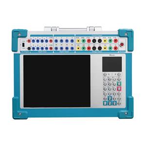
To test the transformer no-load, RDBK-Ⅲ Transformer Load and No Load Tester will be your reliable choice. Click RDBK-Ⅲ to learn more about the product.
With its sleek design and state-of-the-art technology, the Transformer Load and No-Load Tester boasts unparalleled performance and a comprehensive feature set. It utilizes the latest single-chip microcomputer testing technology, combined with advanced A/D synchronous AC sampling and digital signal processing, guaranteeing accurate and reliable measurement data.
To learn more about transformer testing equipment, please click Transformer Testing Solutions
To get the latest quote, please contact us

Characteristics of Transformer Losses
Po——no-load loss, mainly iron loss, including hysteresis loss and eddy current loss;
Hysteresis loss is proportional to frequency; proportional to the power of the hysteresis coefficient of the maximum magnetic flux density.
Eddy current loss is proportional to the product of frequency, maximum magnetic flux density, and thickness of silicon steel sheet.
Pc——load loss, mainly the loss on resistance when the load current passes through the winding, generally called copper loss. Its size varies with the load current and is proportional to the square of the load current; (and expressed by the standard coil temperature conversion value).
Load loss is also affected by the temperature of the transformer. At the same time, the leakage flux caused by the load current will generate eddy current loss in the winding and stray loss in the metal part outside the winding.
Total loss of transformer ΔP=Po+Pc
Transformer loss ratio=Pc/Po
Transformer efficiency=Pz/(Pz+ΔP), expressed as a percentage; where Pz is the output power of the secondary side of the transformer.
Calculation of power loss
The power loss of the transformer consists of two parts: iron loss and copper loss. Iron loss is related to the running time, and copper loss is related to the load size. Therefore, the power loss should be calculated separately.
1. Calculation of iron loss: The calculation formula for iron loss of different models and capacities is: Iron loss (kWh) = no-load loss (kW) × power supply time (hours)
The no-load loss (iron loss) of the distribution transformer can be found in the attached table. The power supply time is the actual running time of the transformer, which is determined according to the following principles:
(1) For users with continuous power supply, the whole month is calculated as 720 hours.
(2) If the power supply is interrupted or the power is limited due to power grid reasons, the calculation is based on the actual number of hours the substation supplies power to the user. It shall not be calculated based on the whole month operation on the grounds that it is difficult to calculate. After the transformer is powered off, the time for the self-dropping fuse tube to be handed over to the power supply station should be deducted when calculating the iron loss.
(3) For users with an accumulation clock installed on the low-voltage side of the transformer, the calculation is based on the accumulated power supply time of the accumulation clock.
2. Calculation of copper loss electricity: When the load rate is 40% or less, it is calculated as 2% of the monthly electricity consumption (based on the reading of the electricity meter). The calculation formula is: copper loss electricity (kWh) = monthly electricity consumption (kWh) × 2%
Because copper loss is related to the load current (electricity), when the monthly average load rate of the distribution transformer exceeds 40%, the copper loss electricity should be calculated as 3% of the monthly electricity consumption. The monthly electricity consumption when the load rate is 40% is checked from the attached table.
The calculation formula of the load rate is: load rate = copy electricity/S. T. Cos¢
Where: S——rated capacity of the distribution transformer (kVA); T——full month calendar time, take 720 hours; COS¢——power factor, take 0.80.
The transformer loss of power transformers can be divided into copper loss and iron loss. Copper loss is generally 0.5%. Iron loss is generally 5~7%. The transformer loss of dry-type transformers is smaller than that of oil-immersed transformers.
Total transformer loss: 0.5+6=6.5 Calculation method: 1000KVA×6.5%=65KVA
65KVA×24 hours×365 days=569400KWT (degrees)
The nameplate on the transformer has specific data.
Transformer no-load loss
No-load loss refers to the power absorbed by the transformer when the secondary side of the transformer is open and the primary side is charged with a sine wave voltage with the rated voltage. Generally, only the rated frequency and rated voltage are paid attention to, and sometimes the tap voltage and voltage waveform, the accuracy of the measurement system, the test instrument and the test equipment are not paid attention to. The calculated value, standard value, measured value and guaranteed value of the loss are confused again.
If the voltage is added to the primary side and there is a tap, if the transformer is a constant flux voltage regulator, the applied voltage should be the tap voltage of the corresponding tap position connected to the power supply. If it is a variable flux voltage regulator, because the no-load loss is different at each tap position, it is necessary to select the correct tap position according to the technical requirements and apply the specified rated voltage, because in the variable flux voltage regulator, a voltage is always applied to each tap position on the primary side.
It is generally required that the waveform of the applied voltage must be an approximate sine waveform. Therefore, one is to use a harmonic analyzer to measure the harmonic components contained in the voltage waveform, and the other is to use a simple method, using an average voltage meter, but the scale is an effective value voltage meter to measure the voltage, and compare it with the effective value voltage meter reading. When the difference between the two is greater than 3%, it means that the voltage waveform is not a sine wave, and the measured no-load loss should be invalid according to the new standard requirements.
For the measurement system, it is necessary to select a suitable test circuit, suitable test equipment and instrument. Due to the development of magnetic conductive materials, the wattage per kilogram loss has dropped significantly. Manufacturers use high-quality high-magnetic conductive grain-oriented silicon steel sheets or even amorphous alloys as magnetic conductive materials. In terms of structure, they have developed step joints and full oblique holes. In terms of process, the non-stacked iron yoke process is used. Manufacturers are developing low-loss transformers, especially no-load losses have been greatly reduced. Therefore, new requirements are put forward for the measurement system. The capacity remains unchanged, and the reduction of no-load loss means the reduction of the power factor of the transformer when it is no-load. A small power factor requires the manufacturer to change and transform the measurement system. It is advisable to use the three-wattmeter method, select a 0.05-0.1 level transformer, and select a wattmeter with a low power factor. Only in this way can the measurement accuracy be guaranteed. When the power factor is 0.01, the phase difference of the transformer is 1 minute, which will cause a power error of 2.9%. Therefore, in actual measurement, the current ratio and voltage ratio of the current transformer and the voltage transformer must be correctly selected. When the actual current is much smaller than the current connected to the current transformer, the larger the phase difference and current error of the current transformer, the larger the error in the actual measurement result. Therefore, the current drawn by the transformer should be close to the rated current of the current transformer.
In addition, in the design, according to the prescribed procedures, the no-load loss calculated by referring to the unit loss and process coefficient of the selected silicon steel sheet is generally called the calculated value. This value should be compared with the standard value specified in the standard or the standard value or guaranteed value specified in the contract. The calculated value must be less than the standard value or guaranteed value, and there should be no margin in the calculation, especially for mass-produced transformers. In addition, the calculated value is only valid for designers or design departments, and has no legal effect. The calculated value cannot be used to judge the loss level of the product. The standard value specified in the standard or the guaranteed value specified in the contract is legally effective. Products that exceed the standard value plus the allowable deviation, or the guaranteed value (the guaranteed value is equal to the standard value plus the allowable deviation) are unqualified products. If there is a loss evaluation system, it will generally be pointed out in the contract, especially for export products, that a fine will be imposed for exceeding the specified loss value, and the fine for no-load loss is the highest. The loss evaluation values of European countries can be found in the 11th issue of "Transformer" magazine in 1994. The fine is several thousand dollars per kilowatt. This is the legal effect and is directly linked to economic benefits.
The concept of measured value should also be correctly understood. Either the reading of the mutual special meter (or the reading of the power converter) or the measured value must be converted to the rated conditions and have sufficient accuracy. For the measured value of no-load loss, it is mainly that the voltage waveform of the power supply must be a sine wave, and the difference between the average voltage meter reading and the effective value voltage reading is less than 3%.
Calculation of no-load loss, load loss, and impedance voltage
No-load loss: When the secondary winding of the transformer is open-circuited and the rated voltage of the rated frequency sinusoidal waveform is applied to the primary winding, the active power consumed is called no-load loss.
The algorithm is as follows: No-load loss = no-load loss process coefficient × unit loss × core
Load loss: When the secondary winding of the transformer is short-circuited (steady state), the active power consumed when the rated current flows through the primary winding is called load loss.
The algorithm is as follows: Load loss = resistance loss of the largest pair of windings + additional loss
Additional loss = winding eddy current loss + circulating current loss of parallel winding wire + stray loss + lead loss
Impedance voltage: When the secondary winding of the transformer is short-circuited (steady state), the voltage applied by the rated current flowing through the primary winding is called impedance voltage Uz. Usually Uz is expressed as a percentage of the rated voltage, i.e. uz=(Uz/U1n)*100%
Turn potential: u=4.44*f*B*At,V
Where: B—magnetic flux density in the core, TAt—effective cross-sectional area of the core, square meters
It can be converted into the commonly used formula for transformer design calculation:
When f=50Hz: u=B*At/450*10^5,V
When f=60Hz: u=B*At/375*10^5,V
If you already know the phase voltage and the number of turns, the turn potential is equal to the phase voltage divided by the number of turns. Transformer no-load loss calculation - Transformer no-load loss composition.
No-load loss includes hysteresis and eddy current loss in the iron core and loss of no-load current on the primary coil resistance. The former is called iron loss and the latter is called copper loss. Since the no-load current is very small, the latter can be ignored. Therefore, no-load loss is basically iron loss.
There are many factors that affect the no-load loss of transformer iron loss. In mathematical formulas, the formula is
Pn, Pw——represents hysteresis loss and eddy current loss kn, kw——constants;
f——frequency of the applied voltage of the transformer in Hz;
Bm——maximum magnetic flux density in the iron core in Weber/m2;
n——Steinmetz constant. For commonly used silicon steel sheets, when Bm=(1.0~1.6) Weber/m2, n≈2. For the currently used directional silicon steel sheets, take 2.5~3.5.
According to the theoretical analysis of the transformer, assuming that the primary induced potential is E1 (V), then: E1=KfBm;
K is a proportional constant, which is determined by the number of primary turns and the cross-sectional area of the core.
Since the primary leakage impedance voltage drop is very small, if it is ignored, then E1=U1
It can be seen that the transformer no-load loss iron loss has a great relationship with the external voltage. If the voltage V is a certain value, the transformer no-load loss iron loss remains unchanged (because f remains unchanged), and because U1=U1N during normal operation, the no-load loss is also called constant loss. If the voltage fluctuates, the no-load loss will change. The iron loss of the transformer is related to the core material and manufacturing process, and has nothing to do with the load size.