Common faults of high-voltage cables, how to repair?
In large and medium-sized X-ray machines, the high-voltage generator and the X-ray tube head are assembled separately and connected through two specially designed multi-core high-voltage cables. The purpose of these cables is to deliver the high voltage output from the generator to the two poles of the X-ray tube and to supply the filament heating voltage to the filament. High-voltage cables carry extremely high voltages and their quality directly relates to the safety of operators and patients. This article provides some experience in repairing high-voltage cables based on common faults and causes, for reference.

1 Common Faults in High-Voltage Cables
1.1 Cable Breakdown
Cable breakdown occurs when the insulation layer is punctured, causing the inside conductor layer to short-circuit with the grounded metal mesh under the high voltage electric field. This forms a short circuit in the high-voltage secondary coil circuit, increasing the secondary current.
① When the insulation layer of a high-voltage cable is completely punctured, the current in the high-voltage secondary circuit increases, and the milliammeter at the center end of the high-voltage secondary may show a sudden pointer movement, excessive reading, impact on the top, or unstable movement, and may reverse and swing down.
② Since the primary current of the high-voltage transformer also increases accordingly, the pressure of the power supply under load increases, and the protective resistance connected in series in the high-voltage primary circuit may overheat or melt, while the fuse in the circuit may also melt, and the overload protection device acts.
③ The brightness of the fluorescent screen significantly dims during fluoroscopy, and the image clarity and contrast during photography significantly decrease, or even no X-ray is generated.
④ If the breakdown is recent, a strong odor of ozone or burnt rubber can be detected near the cable, and a discharge burn hole can be seen at the site of the cable breakdown.
⑤ When the insulation layer of a high-voltage cable is severely punctured, using a high-resistance meter above 1000V to measure the insulation performance between the conductor core and the grounded metal mesh will show a very small resistance value.
1.2 Core Short Circuit
If two cores in the high-voltage cable conductor layer are short-circuited, no abnormalities will be observed at the positive end; however, a series of abnormal phenomena may be caused at the negative end.
① X-ray tube filament heating transformer short circuit: Lightly, it may cause the filament heating voltage to be too low, so the tube current decreases significantly; severely, it may prevent the filament from heating, no X-ray is generated, and the secondary of the filament transformer may overheat or burn due to the short circuit.
② A slight short circuit may cause the X-ray to flicker, and the indication of the milliammeter may be unstable; when shaking the high-voltage cable, the short-circuit resistance may change, making the X-ray generation more unstable.
1.3 Core Open Circuit
It is very rare for all three cores in a high-voltage cable to have an open circuit simultaneously. If an open circuit occurs at the positive end of the cable, it is not significant because the high-voltage socket at the positive end has short-circuited the three cores; however, if it occurs at the negative end, the following phenomena may be caused:
① A slight open circuit can be considered as an increase in the contact resistance in the circuit, so the filament heating voltage decreases, the tube current decreases, and the indication value of the milliammeter is insufficient. When shaking the cable to a certain position, it may be connected again, causing the X-ray to flicker, be unstable, and the filament to flash on and off.
② A complete open circuit means the filament does not light up. If the common wire in the cable cores is open-circuited, both the large and small focus filaments of the X-ray tube light up simultaneously but very dimly, and no X-ray is generated.
2 Causes of High-Voltage Cable Faults
2.1 Manufacturer's Reasons
Reasons for the cable body manufacturing.
Generally speaking, problems that may occur during cable production include insulation eccentricity, uneven insulation shielding thickness, insulation impurities, protruding inside and outside shields, uneven cross-linking, cable moisture, and poor sealing of the cable metal sheath, etc.
Reasons for cable joint manufacturing.
In the past, high-voltage cable joints were of types such as wound, molded, and molded, which required a significant amount of on-site production work. Due to limitations in on-site conditions and production processes, there are inevitable air gaps and impurities between the insulation tape layers, which can lead to problems. In China, the commonly used types are assembled and prefabricated types. Cable joints are divided into cable terminal joints and cable intermediate joints, regardless of the joint type, cable joint faults generally occur at the cable insulation shielding section, because this is the part where electrical stress is concentrated. The causes of cable joint faults are manufacturing defects of the stress cone, insulation issues, and oil leakage from the sealing ring.
Cable grounding system.
The cable grounding system includes the cable grounding box, the cable grounding protection box (with protective layer protector), the cable crossover interconnection box, and the protective layer protector. Generally, the main problems that may occur are caused by poor sealing of the box, which leads to multiple grounding points, causing excessive induced current in the metal protective layer. In addition, the instability of zinc oxide crystals can also cause damage to the protective layer protector.
2.2 Quality of Construction Reason
The on-site conditions are relatively poor, and the factory has higher environmental and process requirements for cables and joints during manufacturing. The temperature, humidity, and dust during construction are difficult to control. During the construction of cables, it is inevitable to leave small scratches on the insulation surface, and semi-conductive particles and particles from sandpaper may also be embedded in the insulation.
In addition, since the insulation is exposed to the air during the construction of joints, it may absorb water, which can leave hidden dangers for long-term safe operation. Installation is not in strict accordance with the process or the process specifications do not consider possible problems. DC voltage withstand test may form an inverse electric field in the joint, causing insulation damage. Due to poor sealing treatment. Intermediate joints must use a metal copper shell and a sealing structure with PE or polyvinyl chloride insulation and anti-corrosion layer to ensure the sealing performance of lead seals during on-site construction.
3 Methods and Steps for Repairing
3.1 Steps for Repairing
Analyze the fault phenomenon of the cable breakdown and determine the cause. Analyze the cause of the high-voltage cable core short circuit fault. Judge the location of the high-voltage cable core open circuit fault. Repair the high-voltage cable plug.
Rui Du M&E is a manufacturer specializing in the production of cable fault testing systems. If you want your cable fault testing to be more accurate and efficient, we recommend our RDCD-II cable fault testing system to you. Product quality is guaranteed, and we are strong Our after-sales service support allows you to have no worries. You are welcome to consult us at any time.

3.2 Steps for Filling the Cable Head
When the cable is punctured, the faulty part must be cut off and refilled. First, prepare the following tools: electrician's knife, file, 150W and 45W soldering irons, each 1 piece, multimeter, 1 piece, steel saw, 1 piece, electric furnace, 1 piece, enamel pot, 1 piece, rosin, solder, appropriate amount, 30mL syringe, 1 piece, ethyl ether or anhydrous alcohol, 500mL, gauze, fine copper wire (for lead wire), etc. Use a syringe to extract an appropriate amount of transformer oil from the generator, and the fine copper wire can be used as lead wire from an electric motor, with the insulating paint removed.
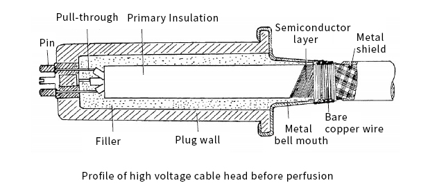
The steps for filling the cable head are as follows. First, measure and record the wiring positions of the small and large focus and common wire at both ends of the cable. Solder the lead wires and metal shielding layer of the plug feet, immerse the plug in heated transformer oil to melt the filler, and remove the plug with force. The cross-sectional view of the high-voltage cable head before filling is shown in Figure

Cut off the faulty part of the cable, remove 1cm of the insulation layer, and expose the cores. According to the length of the cable plug, remove the protective layer and metal shielding layer, file the semiconductor layer (make sure the semiconductor layer can just reach the horn opening of the plug), and file and trim the insulation layer surface to the appropriate size to smoothly insert into the inner hole of the high-voltage plug. Solder three longer copper wires to the cores, and the welding joint between the lead wire and the core should be covered with an insulating sleeve.
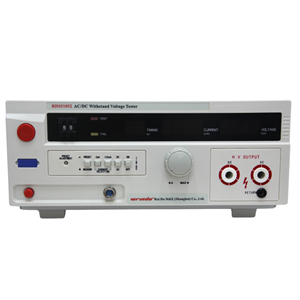
Pass the three welded lead wires through the small holes in the plug feet (make sure the position of the small and large focus and the common wire is correct and smooth). Clean the cable and plug with ethyl ether or carbon tetrachloride, and heat them with a hot air blower. Secure the cable in place so that the cable head is at a 60-70° angle to the ground. Heat the filler (rosin 85%-90%, transformer oil 15%-10%) on the electric furnace to melt it, and then inject it into the plug. Straighten the three leads, and push the high-voltage cable plug into the cable head. Check whether the three leads are short-circuited or open-circuited, and wait for the filler to solidify. Then, solder the lead wires and shielding layer, and perform a voltage withstand test on the repaired cable.
3.3 Points to Note
When removing the protective layer and metal shielding layer, be careful not to damage the insulation layer. When pouring rosin, move slowly and carefully to avoid burns. Ensure the soldering iron has sufficient temperature to avoid cold welds. This detailed translation provides a comprehensive understanding of the common faults in high-voltage cables, their causes, and the steps involved in repairing them, which is essential for X-ray equipment maintenance personnel.


