Primary Current Injection Test Set
Description
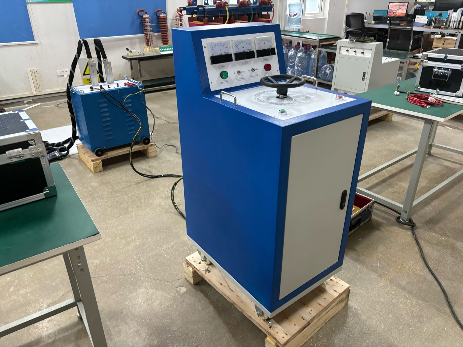
The RDSL series AC and DC Primary Current Injection Test Set are indispensable equipment in electrical commissioning, and they are widely used in power plants, substations, electrical appliance manufacturing, scientific research, and laboratory settings. This series of generators is designed for short-term or intermittent operation, renowned for their compact design, lightweight, excellent performance, and convenient maintenance.
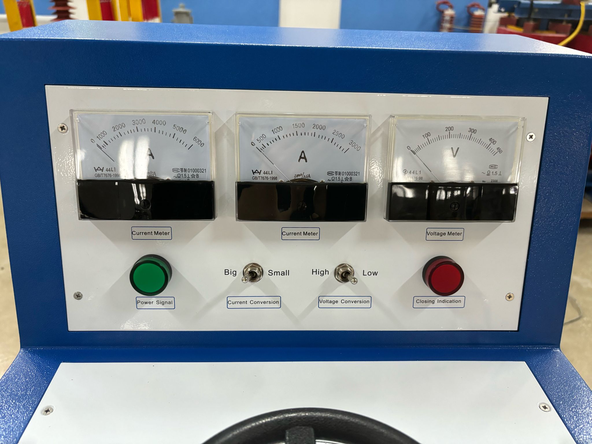
The RDSL series AC and DC Primary Current Injection Test Set adopts a JT-type portable structure, consisting of an indicator instrument panel and an operation panel. The indicator instrument panel is equipped with two current meters of different ranges and a range selection switch and also features a power signal (green indicator light) and a working signal (red indicator light). The operation panel includes start (green button) and stop (red button) buttons and a complete control unit for the working system.
Features
1. Conduct action characteristic tests for various types of switches, circuit breakers, and current relays.
2. Perform accurate calibration operations on panel-mounted ammeters, clamp meters, and current transformers.
3. Designed to be portable, the current output can be adjusted flexibly, supporting bidirectional measurement and allowing for direct reading of both high and low current values.
4. Customizable current output specifications are available to meet specific user requirements.
Main Application
1. Testing and qualification of electrical equipment
(1) Switchgear Testing
The high current generator simulates the high current impact in the actual operation of the power grid, which is used to test the tripping performance and thermal stability limit of switchgear such as high-voltage circuit breakers, fuses, contactors, etc., to ensure that the circuits can be cut off normally in case of faults.
(2) Cable and Busbar Testing
The expected large operating current or even short-time overload current is generated by the high current generator to evaluate the current-carrying capacity and thermal stability of cables and busbars, and to verify their performance under long-term operation or transient conditions.
2. Power Plant and Substation Commissioning
(1) Excitation system test
During generator start-up, the high current generator provides the initial excitation current to help the generator establish the magnetic field and start operation.
(2) Protective Relay Calibration
Apply a specified high current signal to the protection circuit to verify the accuracy and sensitivity of the relay protection device.
3. Electrical product development and quality verification
(1) Motor and Transformer Testing
At the R&D stage, load tests are conducted using high current generators to check the temperature rise, efficiency and heat dissipation performance of motor windings; for transformers, short-circuit impedance, temperature rise characteristics and full-load stability are tested.
(2) New energy battery and charging facilities testing
For electric vehicles, energy storage systems, etc., high-current generators simulate extreme charging and discharging scenarios to assess the safety, life and fast charging and discharging performance of battery packs.
4. Teaching research and simulation
In the teaching and research of electric power engineering, the high current generator is used as an important experimental tool in the analysis of dynamic characteristics of power systems and the study of the performance of power electronic devices, providing support for academic and scientific research.
Operation Instructions
1. Wiring preparation
First, connect the booster and the equipment to be tested correctly according to the commissioning requirements. Ensure that all wiring is correct, and then connect to the power supply.
2. Select the current level
According to the current strength required by the equipment to be tested, adjust the current transfer switch to the appropriate position of “large” or “small”. Note that, because the current transformer is not allowed to open circuit, the switch position should not be placed in the middle. For larger power equipment, through the series and parallel short-circuit piece of the position adjustment, to realize the conversion of large current gear.
3. Start the equipment
Close the power switch and observe that the green light comes on. Subsequently, press the start button, the green light goes out and the red light comes on. At this time, slowly rotate the regulator handle clockwise to gradually raise the current to the desired test value.
4. Stopping the test
After the test is completed, turn the regulator handle counterclockwise to zero it. Then press the stop button, the red light goes out and the green light comes back on, marking the end of the test.
Precautions for use
1. Safe handling and staffing
As the equipment is heavy, it must be moved with care to ensure personal safety. At least two people are required to carry out the test, one to operate the equipment and the other to supervise to ensure the operation process is safe and error-free. Maintain an appropriate safe distance from the test article and wear personal protective equipment. At the same time, set up a clear warning area.
2. Equipment grounding
The equipment shell must be reliably grounded, even when working at low voltage, and must not be neglected to prevent potential personal safety accidents. Ensure that the instrument is well grounded and that the step-up transformer and operating table are reliably grounded to ensure safe operation.
3. Conductor connection
The wire from the secondary of the step-up transformer to the test piece should not be too long, the cross-sectional area should be enough (refer to the current density of 68A/mm²), and make sure that the contact surface is clean (can be polished with fine gauze), in order to prevent the joints from being overheated or the current cannot reach the rated value.
4. Power supply check
Before starting work, check whether the power supply has enough capacity to avoid overheating of the power cord or voltage reduction, which may affect the normal operation of the equipment.
5. Working environment
Ensure that the work site is free of flammable materials. When conducting the temperature rise test, there should be enough fire extinguishing equipment. During the continuity test, someone needs to be on duty and check the heating condition of the temperature rise source equipment, wires, and connectors regularly and make records. Pay attention to adjusting the TD to maintain the rated test current according to the change in grid voltage.
6. Abnormal handling
If any abnormality is found during the test, turn off the air switch power immediately and continue the test after the cause is identified. After the test, be sure to zero the regulator and cut off the power supply according to the air switch, then remove the test wiring to ensure safety.
7. Comply with the regulations
The test work should comply with the relevant provisions of the Electricity Industry Safe Working Procedures and develop practical safety measures. Remember that the high current generator is designed to work for short periods of time, so prolonged operation at rated capacity is not permitted, and in particular, exceeding the rated current is prohibited to prevent overheating of the equipment.

