Reasons why the series resonance test device cannot rise to the set target voltage
Although the series resonance test device has undergone strict quality inspection before leaving the factory, various faults may still be encountered during the test due to the complex and changeable on-site environment. The above content provides analysis and treatment suggestions for common faults to help testers solve problems more quickly and accurately. Regular maintenance and calibration of equipment can not only extend the life of the equipment but also ensure the efficiency and safety of the test. For complex faults, it is still recommended to consult professionals to ensure equipment and personnel safety.

1. The system resonance point is not within the output frequency range
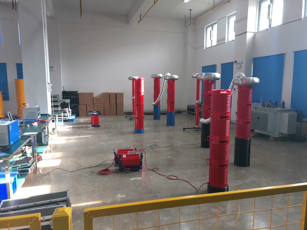
Cause analysis: The series resonance test device is based on the LC resonance principle. During the test, the resonance point of the system should be within the output frequency range of the equipment. During the field test, due to the deviation of the reactor and capacitor parameters, or the capacitance fluctuation of the test product, the resonance frequency may deviate from the adjustable range, resulting in the inability to reach the resonance state, thereby hindering the boost.
Solution: It is recommended that engineers pay attention to confirming that the equipment resonant frequency is within the adjustable frequency range through tests when adjusting the reactor and capacitor parameters. System matching can be achieved by adding compensation capacitors or fine-tuning the excitation voltage. It is recommended to equip standard capacitors in the early stage of debugging to accurately find the resonance point and improve the boost efficiency and test success rate.
2. System wiring error
Cause analysis: The wiring relationship of the series resonant device is complicated, and any wrong connection will cause the circuit to not work properly. In particular, the connection error between the variable frequency power supply signal line and the voltage divider sampling signal column will cause the device to be unable to obtain voltage feedback, affecting the boost process.
Solution: Engineers should strictly follow the circuit diagram when wiring, especially the wiring details of the high-voltage and low-voltage ends. Multiple reviews should be conducted before the test to ensure that each wire is connected correctly, especially the signal acquisition part. It is recommended to check each connection node step by step to avoid equipment failure due to wiring errors.
3. Poor grounding
Cause analysis: Grounding is the basis for ensuring the normal and safe operation of power equipment. If the grounding is poor, it will lead to unstable voltage feedback, frequent device protection action, and other problems, which will affect the normal progress of the boost test. Poor grounding is particularly important in high-power equipment, especially the cable grounding problem at the high-voltage end.
Solution: When making grounding connections, field engineers should use appropriate grounding rods and wires to ensure that the grounding resistance meets the standard requirements. During the test, it is recommended to equip a grounding resistance tester to monitor the grounding status in real-time. Regular cleaning and maintenance of the contact surface of the grounding components will help improve the grounding quality of the equipment.
4. High voltage sampling feedback signal problem
Cause analysis: High-voltage sampling signals are crucial to the voltage feedback of the system. If the sampling line is open, loose, or unreliably connected, the control system will not be able to obtain the true voltage value, resulting in unstable or blocked voltage boost.
Solution: When installing the sampling feedback signal line, ensure that it is firmly and reliably connected. If there is signal fluctuation on site, check whether the connector is intact and replace damaged connectors or cables in time. It is recommended to calibrate the sampling system regularly to ensure accurate signal feedback to ensure the stability of the test.
5. Internal failure of the test product
Cause analysis: If the test product has insulation aging or internal defects, it will lead to increased voltage loss and it will be difficult to reach the predetermined boost value. Especially in aging equipment or equipment with poor storage environment, the degradation of insulation materials will increase the system load and affect the boost effect.
Solution: Before boosting, it is recommended to use an insulation tester to test the insulation of the test product to eliminate the possibility of internal defects. If problems are found inside the equipment, the defective parts should be repaired or replaced in time to avoid affecting the test process due to equipment failure.
6. The capacitance of the reactor does not match that of the test product
Cause analysis: The mismatch between the test capacitance and the reactor parameters will cause the system to be unable to find a suitable resonance point. If the capacitance deviation is too large, it is difficult for the system to reach the optimal working state, which directly affects the boost effect.
Solution: The resonance point of the system can be found by replacing or adjusting the compensation capacitor parameters and matching the capacitance of the test product. Engineers need to measure and verify the reactor and capacitor parameters multiple times in the early stage of the test to ensure that the equipment works at the resonance point.
7. The output voltage of the excitation transformer is low
Cause analysis: The excitation transformer is the voltage source of the system. If the output voltage is insufficient due to parameter settings or internal faults, the system will not be able to boost the voltage normally. Insufficient input voltage of the transformer or short circuit of the internal winding may affect the output voltage.
Solution: Check whether the input and output parameters of the excitation transformer meet the requirements and confirm that it works within the rated range. If the output voltage is found to be low, adjust the input voltage or replace the excitation transformer. For excitation transformers used for a long time, it is recommended to conduct insulation resistance and transformation ratio tests regularly to ensure its stable performance.
8. External interference factors
Cause analysis: External magnetic fields, temperature fluctuations, unstable power supply voltage and other factors can interfere with the system, especially in outdoor test environments, where external factors may significantly affect the performance of the booster.
Solution: In field tests, engineers should try to choose a stable environment, reduce strong magnetic field interference, and monitor voltage fluctuations in the power supply system. If possible, add shielding measures to reduce external interference. In addition, the field ambient temperature should also be controlled within the operating temperature range of the equipment.
Although the series resonance test device has undergone strict quality inspection before leaving the factory, due to the complex and changeable on-site environment, various faults may still be encountered during the test. The above content provides analysis and treatment suggestions for common faults to help testers solve problems more quickly and accurately. Regular maintenance and calibration of equipment can not only extend the life of the equipment, but also ensure the efficiency and safety of the test. For complex faults, it is still recommended to consult professionals to ensure the safety of equipment and personnel.


