What are the methods of power cable fault detection and diagnosis and treatment?
Cables are susceptible to faults caused by insulation aging, insulation moisture, cable overheating, mechanical damage, sheath corrosion, overvoltage, material defects, intermediate joints and terminal head design and manufacturing process problems during normal operation and maintenance operations. There are different ways to deal with different types of faults. Fault detection is based on the detected fault conditions to determine the nature of the fault and fault point. Currently, the common methods of coarse fault point detection are the bridge method and wave reflection method. Through fault location, the operation and maintenance personnel can then repair the fault so that the cable can return to normal operation.
The insulation resistance of one or several cores of the cable to ground or between the core and the core is less than a few thousand ohms, and the continuity of the conductor is good. Generally common are single-phase ground, two-phase or three-phase short circuit, two-phase or three-phase grounding.
1. Cable fault detection and diagnosis
(1) High-impedance grounding or short-circuit faults: cable a core or several cores to the ground insulation resistance or insulation resistance between the core and the core value is much lower than the normal value, but the continuity of the conductor is good. Generally common single-phase grounding, two-phase or three-phase short circuit grounding.
(2) Broken line fault: cable core insulation is good, but there is a core or several core conductor discontinuity.
(3) Disconnection and ground fault: cable has a core or several core conductor discontinuity, and by the resistance to ground.
(4) Flashover faults: most of these faults occur in the preventive voltage test, and more in the cable intermediate joints or terminals. When this type of failure occurs, the fault phenomenon is not necessarily the same.
(5) The difference between low-resistance faults and high-resistance faults: the above five types of faults, low-resistance and high-resistance is not absolutely fixed, it is mainly determined by the fault detection method, the conditions of the detection equipment and the size of the conductor resistance of the cable being tested. Currently used cable flaw detector test voltage up to 600 V, when the cable conductor circuit resistance of 1 Ω or less, the allowable fault resistance value of up to 100 kΩ. Obviously, the lower the test voltage or cable conductor circuit resistance is smaller, the allowable fault resistance value is lower. Measurement of high-resistance faults, you must increase the test voltage or increase the sensitivity of the current detector. The fault resistance is generally considered to be below a few thousand ohms for low resistance faults. When using the low-voltage pulse method or flashover method to find cable faults, usually considered 100 Ω low-resistance faults and high-resistance fault demarcation line.

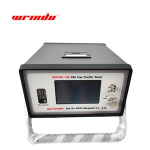
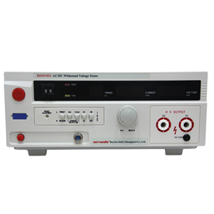
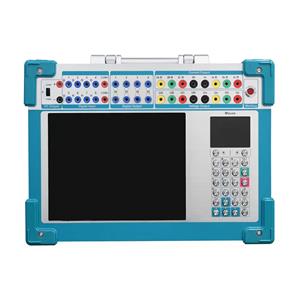
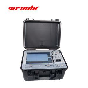
RDCD-Ⅱ Cable Fault Testing System is the achievement of our company's continuous improvement and innovation for many years. The product is the leading product of cable fault testing instruments at home and abroad at present, applying modern power electronic technology. It can also measure low resistance, short circuit, open circuit and broken line faults, high resistance leakage and high resistance flashover faults of various high frequency coaxial cables, local telephone cables, street lamp cables and buried wires with different cross sections by using the distance measurement, path finding and location of the main insulation fault points of power cables with voltages of 35kV and below.
Click on the product model number RDCD-II for more product information.
Click Contact Us for a detailed product quote.
2. The cable fault characterization and measurement of the search steps
(1) Fault characterization: the so-called fault characterization, that is, to determine the fault resistance is high resistance or low resistance; is flashover or closed flashover fault; is grounded, short-circuited, disconnected, or a combination of them; is a single-phase, two-phase, or three-phase fault. Usually can be based on the phenomenon that occurs when the fault occurs, the initial determination of the nature of the fault. When the fault phenomenon can not be fully determined by the nature of the fault down, but also must measure the insulation resistance of the cable and the conductivity of the core test.
(2) Cable fault measurement and search steps: after determining the nature of the fault, you can use a variety of means to find the fault point. In order to facilitate the operation and maintenance personnel to carry out maintenance.
2.1 General fault detection steps
Step1: Determine the nature of the fault.
Step2: Burn through the fault point, if the fault resistance is very high, by applying shock voltage or AC voltage burn through the fault point, the high resistance fault or flashover fault into a low resistance fault, in order to carry out a rough test.
Step3: Coarse measurement, that is, to measure the length of the fault point to any end of the cable.
Step4: Detect the laying path of the faulty cable line, for directly buried, rows of pipes, sand-filled cable trench laying cable is to find out the laying path of the faulty cable and the depth of burial, in order to carry out the precise measurement of the fixed point.
Step5: Fault location, is the use of acoustic measurement, induction, step voltage and other methods for the precise location of the fault point.
The above five steps is a general search steps, not fixed, the actual work can be based on the specific circumstances of some of the steps omitted.
2.2 Burn-through of cable fault point
With the large number of applications of cross-linked polyethylene cables and the strengthening of insulation supervision, the number of faults occurring in the operation of cables is gradually decreasing, while the number of faults in the test is relatively increasing. In addition the faults caused by external damage, although greatly reduced than before, but the proportion of the total number of faults is still very high.
According to the statistics of the relevant operating units [4], the fault resistance of the test breakdown point is generally very high, more than 90% of high resistance faults, in the cable operation of insulation aging and external damage caused by the fault, high resistance faults also accounted for more than 70%. Therefore, in the occurrence of cable faults, high resistance faults stand the vast majority. But a lot of rough measurements, fixed-point methods and measuring instruments must be used at lower resistance, which requires high resistance faults to be burned through the processing, so that the high resistance becomes low resistance, in order to facilitate the measurement.
Cable fault point burn-through method has AC burn-through, DC voltage burn-through and shock voltage burn-through three. AC voltage burn-through needs to provide reactive current to the fault cable, so the capacity of the burn-through equipment must be large enough. The use of AC burn-through method, due to the frequency current in a cycle to two times over zero, each time over zero insulation has recovered, the fault resistance increases rapidly, the fault point is easy to be burned off. Therefore, when there is no need to burn the fault resistance to 100 Ω or less, generally do not use the AC burn-through method. Impulse voltage burn through the capacity requirements of the equipment is not large, easy to realize, but the burn time is relatively long.
(3) fault location
Cable fault localization is to find the fault point. Divided into the rough measurement of the fault point and fault point localization [4].
3.1 Rough measurement of the fault point
Rough measurement of the fault point is to measure the distance from the fault point to any end of the cable, this step is a prerequisite for fault location. Coarse measurement method has many kinds, according to the basic principle is summarized in two categories: one type of bridge method, another type of wave reflection method.
3.1.1 Bridge method
Bridge method is divided into low-voltage bridge method and high-voltage bridge method. The use of cable core resistance on both sides of the fault point and the proportion of resistance constitutes Whitestone/Murray bridge is the traditional classic detection method. Figure 1 is the schematic diagram of this type of detection method.
Set to be measured at both ends of the cable distance from the fault point for L1 and L2, the cable length of L, their corresponding core resistance for R1 and R2, obviously R1/R2 = L1/L2; access to the bridge after the composition of the circuit shown in Figure 2. In the figure r1 + r2 = r0 for the proportional potentiometer, its resistance value corresponds to the dial reading P. After balancing there is R1/R2 = L1/L2 = r1/r2; and L1/L = r1/r0 = P%, so there is L1 = L・P%.
3.1.2 Wave reflection method
The wave reflection method is divided into primary pulse method (low voltage pulse method), secondary pulse method, arc reflection method, and tertiary pulse method [6-8]. The pulse wave propagates in the cable at a certain speed, and is reflected at the cable breakdown point or cable end. The wave reflection method is based on the time difference of the pulse to locate, and has a wide range of application, which can locate the unknown cable length and disconnection faults. As Figure 3 is the principle of pulse reflection.
3.2 Fault location
Cable operation or maintenance technicians according to the results of the cable fault pre-location, in the vicinity of the cable fault point, through the instrument and equipment to the location of the cable fault point for the precise positioning process. The conclusion of this step is to point out the location of the fault point within 0.1 meters. The commonly used methods are acousto-magnetic synchronization, step voltage method and audio induction method.
3.2.1 Acoustic-magnetic synchronization method
The principle wiring of acoustic-magnetic is the same as the wiring diagram of the impact voltage burn-through fault point. DC high voltage to capacitor charging so that the ball gap breakdown, the voltage will be added to the point of failure, so that the fault click through the spark discharge, causing electromagnetic wave radiation and mechanical audio vibration. The principle of the acoustic-magnetic synchronization method is to use the mechanical effect of the discharge, pick up the vibration wave with the acoustic receiver probe on the ground, and determine the fault point according to the strength of the vibration wave.
3.2.2 Step voltage method
The step voltage method has a good detection effect on cable sheath faults. Therefore, it is mainly an effective means of locating cable sheath faults. Principle shown in Figure 4, in the fault cable metal sheath on the application of a negative polarity DC voltage, from the G point of the current flowing into the soil to form a "V" shaped potential distribution, step-by-step voltage method is precisely through the probe to find the lowest point of the potential in the soil to determine the location of the fault point. On both sides of the fault point. The ground potential difference is opposite, the closer the fault point the smaller the potential difference.
3.2.3 Audio induction method
Audio induction method is generally used for fault resistance less than 10Ω low resistance fault fixed point. When the acoustic-magnetic synchronization method for the fixed point, due to vibration sound propagation is shielded, or outside vibration interference is very large, as well as very low grounding resistance, especially metallic grounding fault faults at the fault point is simply no discharge sound and can not be fixed point, the need for audio induction method for the fixed point.
The basic principle of the audio induction method is the same as the principle of the audio induction method of detecting cable paths. Detection, with a 1kHz audio signal generator to the cable to be tested through the audio current, sending electromagnetic waves. Then on the ground with a probe along the cable path to accept the cable around the electromagnetic field changes in the signal, and sent to the amplifier to amplify. Then the amplified signal is sent to the headset or indicator, according to the strength of the sound in the headset or the indicator indicates the size of the value of the location of the fault point. At the point of failure, the audio signal in the headset sounds the strongest. When the probe is moved 1 to 2 m from the fault point, the audio signal sound is interrupted, then the strongest audio signal sound is the fault point.
(4) Conclusion
In summary, the Murray bridge, which is composed of cable core resistance and proportional resistance on both sides of the fault point, is a traditional and classic localization method when roughly measuring the fault. The equipment thus constituted is inexpensive and simple to operate. Due to the low voltage measurement of the low voltage bridge method instruments in the past, usually considered unsuitable for high resistance.
The high voltage bridge completely solves the limitations of the bridge method for high resistance localization. The advantages of the bridge method are no blind spots, accuracy, and ease of use. The low-voltage pulse method of the wave reflection method is suitable for low-resistance ground faults from 0 to 1 kΩ, and for high-resistance ground faults, the high-voltage pulse signal is first used to instantly break through the high-resistance, and then the arc-reflection method or the low-voltage pulse signal is used to quickly measure the reflected signal from the fault point and then to detect the fault point information. The above methods have their own applicable environment, for some complex faults, the combination of the above methods can be used to obtain the best detection results.