A brief discussion on the important role of transformer oil chromatography analysis
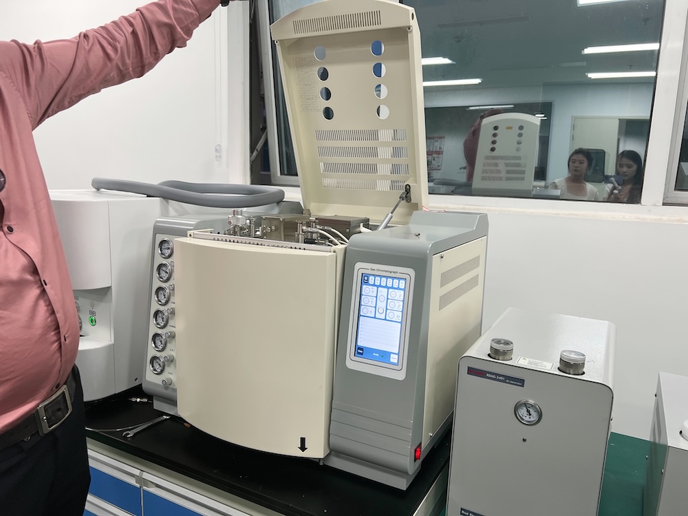
Gas chromatography is a physical separation analysis technology. The analysis procedure first separates the gas dissolved in the sampled transformer oil through a vacuum pump degassing device. It then quantitatively injects it into the chromatograph analyzer with a syringe. The gas flows through the chromatographic column under the impetus of the carrier gas. After the chromatographic column separates the mixed gas, it is detected by the identifier. The separated gas components flow through the identifier one by one in a particular order to convert the gas concentration into an electrical signal, which is then recorded by the recorder and arranged into pulse peaks in the order of each component to form a chromatogram. A pulse peak represents a gas component, and the peak's height or area reflects the gas's concentration. The chromatogram analyzes the gas being analyzed qualitatively and quantitatively, then calculates each gas component's concentration using the peak height. Dissolved gas analysis in oil includes collecting oil samples, test analysis, and fault judgment.
1.Sources of dissolved gases in oil inside oil-filled electrical equipment
1.1 Dissolution of air
Generally, the main components of dissolved gas in transformer oil are oxygen and nitrogen (including a small amount of argon), which are all derived from the dissolution of air in oil. The total gas content in oil is related to factors such as the sealing method of the equipment and the degree of degassing of the oil. The saturated content of air dissolved in oil is generally about 10%, but its composition differs from that of air. Other components of dissolved gas in transformer oil, such as CO2 and H2, may sometimes be brought in from outside by air or other reasons (such as the CO2 filled into a newly installed transformer during transportation is not completely removed or the nitrogen of a nitrogen-filled transformer contains contaminated impurities, etc.).
1.2 Gases generated under regular operation
The insulating oil and solid insulating material inside the transformer will age slowly over time due to the effects of the electric field, heat, humidity, and oxygen during regular operation. In addition to some non-gaseous degradation products, a small amount of hydrogen, low molecular weight hydrocarbon gas, and carbon oxides will also be produced. Carbon oxides (CO, CO2) have the most significant components, followed by hydrogen and hydrocarbon gases. According to statistical analysis, the gases generated in ordinary operating transformers have the following phenomena:
① Hydrocarbon gas: The total hydrocarbon C1-C2 in the oil is generally less than 150ul/L, but the C1-C2 hydrocarbon gas increases significantly in transformers that have been used for a long time;
② Hydrogen: The hydrogen content in the oil is generally less than 150ul/L, but some transformers and capacitive bushings have high hydrogen content due to poor manufacturing process or unstable oil quality;
③ Carbon oxides: The content of CO and CO2 in the oil is related to the operating years of the equipment. The regularity of the change in CO2 content is not strong, except that it is closely associated with the transformer structure, the insulation material properties, the operating load, and the oil protection method.
④ Newly commissioned transformers, especially domestic transformers, often rapidly increase H2, CO or CO2 in the early stage of operation due to the manufacturing process or the material insulation material used. Still, it will gradually decrease after reaching a specific limit of increase.
1.3 Gas generated under fault
If the flammable gas dissolved in the transformer oil is large in volume and fast, it is caused mainly by equipment failure. These fault gases are generated by the cracking of insulating materials under heat, electricity and mechanical stress. Transformer oil and fibre insulation materials age and decompose under the influence of moisture, oxygen, heat and catalysis of materials such as copper and iron during operation. Most of the gases produced are dissolved in the oil, but the gas production rate is slow. When an initial fault or a new fault condition is formed inside the transformer, its gas production rate and gas production are very obvious. Most of the initial defects will show early signs. Therefore, properly analyzing the gas the transformer produces can detect the fault.
According to the needs of internal fault diagnosis of oil-filled electrical equipment, the objects of analysis of dissolved gas components in insulating oil generally include permanent gases (H2, O2, N2, CO, CO2) and gaseous hydrocarbons CH4, C2H6, C2H4, C2H2) for a total of nine components. Since transformer oil has no explicit requirements for oxygen, we ignore this item in the analysis and only detect the remaining eight components.
2. Experimental elements
2.1 Requirements for sampling locations
The sampling point for transformer oil is generally the sampling valve at the bottom of the transformer. Due to the circulation of oil flow, the gas distribution in the oil is uniform. For safety reasons, sampling should be done at the bottom so that the oil sample is representative. If there are exceptional circumstances, please pay attention to the following:
① In case of severe faults and large gas production, SamplingSampling can be done at the upper and lower parts at the same time to understand the nature and development of the fault;
② When water is found at the bottom of the transformer or the hydrogen content of the oil sample is abnormal, SamplingSampling should be done at the upper part or other parts;
③ SamplingSampling should be done during equipment operation. Suppose the equipment has been shut down or just started. In that case, the oil convection may be insufficient, and the escape of fault gas or insufficient exchange with the oil flow should be considered, which may affect the measurement and diagnosis results.
2.2 Requirements for sampling containers
The container wall is airtight or gas-absorbent, preferably transparent so that the sample condition can be observed easily; there are no dead corners in the container, and no bubbles remain; it has good tightness and can completely isolate the air during SamplingSampling and no air escapes or is inhaled after SamplingSampling; the design can freely compensate for the volume change caused by the thermal expansion and contraction of the oil sample with temperature so that a negative pressure cavity is generated inside the container to absorb the bubbles; the material is chemically stable and not easy to break, which is convenient for storage and transportation. According to the above requirements, all-glass syringes with a volume of 100ml that meet domestic and international standards are used as sampling containers. When selecting, they must be strictly inspected first; the syringe must be cleaned and dried before use, and the syringe core plug should be able to slide freely without jamming; after SamplingSampling, the syringe should continue to be kept clean, and dust and damage prevention should be paid attention to.
2.3 Method of taking oil samples
General precautions include: the residual oil in the sampling valve should be removed as much as possible, and the dirt around the valve body should be wiped clean; the sampling connection method should be reliable, without oil leakage or air leakage defects; before SamplingSampling, the air in the sampler and the connection system should be exhausted; during the sampling process, the oil sample should flow into the container smoothly without impact, splashing or foaming; when taking oil samples from sealed equipment under negative pressure, harmful pressure air intake should be prevented; special attention should be paid to keeping the syringe core clean to prevent jamming; pay attention to personal safety during SamplingSampling, especially for live equipment and SamplingSampling from high places;
2.4 Personnel operation
Due to the small content of some fault characteristic gases (such as H2, C2H2, etc.), it is required to detect High sensitivity and minor measurement errors; to adapt to the development of monitoring equipment failure, the analysis operation needs to be simplified and fast; sample gas analysis:
① Degassing: The oscillation degassing method is used;
② Calibration: The standard gas is valid for one year and should not be used after the expiration date. The component concentration should not be too large or too small and should be as close to the sample gas concentration as possible to reduce quantitative errors. When calibrating, pay attention to ensure that the repeatability of the second or more times is within 1.5%. The calibration must be carried out when the instrument is stable. Generally speaking, the instrument is calibrated once each time it is turned on for analysis. If the instrument has poor stability or the operating conditions change suddenly, the calibration frequency must be increased.
③ Sample gas analysis: The injection and calibration operations should be the same as the three fasts and defences. That is, "three fasts": insert the needle quickly and accurately; push the needle quickly (moving the needle quickly to inject the sample as soon as the needle is inserted to the bottom); remove the needle quickly (pause for a while after injecting the sample and then quickly withdraw the needle). "Three protections": prevent leakage of sample gas (the syringe must be strictly checked for tightness; the silicone rubber pad of the injection port must be replaced frequently; prevent the pressure before the column from being too large and rushing out of the syringe core; prevent the syringe needle from being blocked, etc.); prevent sample gas distortion (do not extract gas samples under negative pressure to avoid bringing in air; reduce the influence of the "dead volume" of the syringe, such as using a syringe quantitative clamp, flushing the syringe with sample gas, using the same syringe for injection, etc.); prevent changes in operating conditions (operating conditions such as temperature and flow are stable; use the same syringe, the same injection volume, and the same instrument signal attenuation block for calibration and analysis samples, etc.). The repeatability of the injection gas is the same as that of the calibration. During calibration, the remaining gas must be exhausted before taking the gas; after marking the sample, wash the needle with air. The method to judge the cleanliness is to use the injected air sample to see whether it contains C2H2 content to prove it. Thereby ensuring the accuracy of the data.
3. Chromatographic detection failure analysis method
3.1 Accumulation of gas production rate under fault
Most of the flammable gas generated by latent faults of oil-filled electrical equipment will dissolve in the oil. As the fault continues, the gas accumulates in the oil until it is saturated, or even bubbles are precipitated. Therefore, the content of fault gas in the oil and its accumulation degree is a basis for diagnosing the existence and development of the fault.
3.2 Characteristics of gas production under fault
The gas generated inside the transformer under different faults has different characteristics, which is another basis for diagnosing the existence and development of the fault. For example, if the total hydrocarbon is high, C2H2 < 5ppm, it is a general overheating fault; if the total hydrocarbon is high, C2H2 > 5ppm, but C2H2 does not constitute the main component of the total hydrocarbon, the H2 content is high, and it is a severe overheating fault; The total hydrocarbon is not high, H2 > 100ppm, CH4 is the main component of the total hydrocarbon; it is a partial discharge fault; the total hydrocarbon is not high, C2H2 > 10ppm, and the H2 content is high, it is a spark discharge; the total hydrocarbon is high, the C2H2 content is high, and it constitutes the main component of the total hydrocarbon, and the H2 content is high, it is an arc discharge; in addition, water ingress and moisture in the equipment is also an internal latent fault, which can be judged by gas analysis. At the same time, the oil temperature and load of the transformer are tested. The temperature has no apparent upward trend, but due to the long fault operation time, hot spots often exist in the solid insulation, which will cause insulation degradation and pyrolysis, which is more harmful to the insulation. Hot spots usually develop from low to high temperatures and even rapidly develop into arc hot spots, causing equipment damage accidents. Some bare metal hot spots generally burn out the core, bolts, and other components; severe cases can also cause equipment damage. As the transformer runs longer, the transformer may have initial faults. Some flammable gases in the oil are a precursor to internal faults. These combustible gases can reduce the flash point of the transformer oil, causing early faults. Transformer oil and fibre insulation materials age and decompose during operation due to the effects of moisture, oxygen, heat, and the catalytic impact of materials such as copper and iron. Most of the gases produced are dissolved in the oil, but the gas production rate is relatively slow. When an initial fault inside the transformer or a new fault condition is formed, its gas production rate and gas production are undeniable. Most of the initial defects will show early signs. Therefore, properly analyzing the gas produced by the transformer can detect the fault.
4. How to deal with internal faults in transformers
Take oil samples for observation, conduct external inspections such as the presence of suspended particles and aromatic odour, and perform chromatographic analysis of the gas dissolved in the oil; examine the development trend of the fault, that is, the gas production rate of the fault point (if any), which is related to the amount of energy consumed by the fault, the fault location, the temperature of the fault point, etc.; when it is believed that there is a fault inside the transformer, the three-ratio method can be used to judge the type of fault; in the case of gas inside the gas relay, the analysis results of the gas sample inside the relay should be compared with the analysis results of the gas taken out of the oil.
In summary, the critical role of chromatography in the safe operation of electrical equipment is irreplaceable. Using gas chromatography to analyze the gas in transformer oil and monitor the equipment's operation, the transformer fault's location and the type of internal fault can be diagnosed. Transformer oil is easily affected by various factors during operation, and corresponding preventive measures can be taken to prevent the occurrence of internal transformer faults, prevent and repair in advance, avoid safety hazards, and provide strong guarantees for improving the safe operation of equipment.


