Measurement Method of Transformer DC Resistance
The DC resistance of a transformer refers to the DC resistance value of each phase winding. The purpose of measuring the DC resistance of a transformer is to check the welding quality of the winding joints and whether there is a short circuit between the winding turns; to check whether the contact of the tap changer is good and whether the actual position of the tap is correct. When the transformer is overhauled or the tap position is changed, or there is a short circuit due to a fault in the outgoing line, it is necessary to measure the DC resistance of the winding together with the bushing.
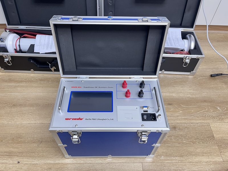
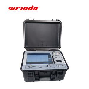
In order to meet the needs of fast measurement of transformer DC resistance, our company developed RDZR-50A DC Resistance Tester. The instrument adopts new power supply technology, which has the characteristics of small volume, light weight, large output current, good repeatability, strong anti-interference ability, perfect protection function and so on.
For detailed product parameters, please click RDZR-50A.
For the latest quote, please contact us.
1. DC resistance measurement method
The measurement methods of transformer DC resistance include current-voltage meter method, DC bridge method, and constant current source bridge method.
1. Current-voltage meter method
1) The current-voltage meter method is also called the voltage drop method. Its principle is to pass a DC current through the measured resistor and measure the voltage drop on the resistor. According to Ohm's law, in the same circuit, the current in the conductor is proportional to the voltage across the conductor and inversely proportional to the resistance of the conductor. The measured resistance value can be calculated.
2) When using the voltage drop method to measure DC resistance, the ammeter should use an ammeter with a small internal resistance, and the voltmeter should use a voltmeter with a large internal resistance; the accuracy level of the measuring meter should not be lower than level 0.5.
2. DC bridge method
1) The DC bridge method is a method of measuring DC resistance by applying the DC bridge balance principle. Commonly used DC bridges include single-arm bridge, double-arm bridge, and DC digital bridge.
2) When measuring DC resistance, the selection of instruments should consider the size of the test current, the measurement range of the measuring instrument, and the nature of the test object to improve the accuracy and stability of the measurement. When measuring DC resistance, the test equipment should be in a cold state, and the temperature of the test object should not be significantly different from the temperature of the surrounding air.
3) Due to the large inductance of the transformer, when measuring DC resistance, the self-induced electromotive force of the power supply is very high at the moment of connection and disconnection. The DC resistance should be measured after the transformer is powered off, the high-voltage lead is removed, and it is fully discharged. When measuring the DC resistance of the winding of a large high-voltage transformer, other windings of various voltage levels that are not tested should be short-circuited and grounded to prevent high voltage from being generated when the DC power supply is turned on or off, which may endanger the safety of equipment and personnel.
4) For large-capacity power transformers, since the charging time constant of the series circuit is very large, each measurement requires a long time to wait for the current and voltage meter indications to stabilize, so the working efficiency is very low. Special instruments such as constant current power supplies are often used to replace the power supply, which can greatly shorten the test time.
5) When the three-phase transformer has no neutral point lead-out line, the line resistance can be measured and then the resistance of each phase can be calculated.
2. Test standard of transformer DC resistance
For transformers above 1600kVA, the difference between the DC resistance of each phase winding should not be greater than 2% of the three-phase average value. For windings without neutral point lead-out, the difference between the lines should not be greater than 1% of the three-phase average value.
For transformers of 1600kVA and below, the difference between the DC resistance of each phase winding is generally not greater than 4% of the three-phase average value. For windings without neutral point lead-out, the difference between the lines is generally not greater than 2% of the three-phase average value.
Compared with the previous measured value of the same part (converted to the same temperature), the change should not be greater than 2%.

