Very Low Frequency VLF Hipot Tester

- Wrindu
- Shanghai, China
- about 25 days
- 5000 set/month
- RDVLF-80
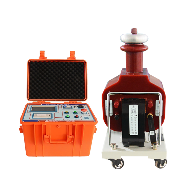
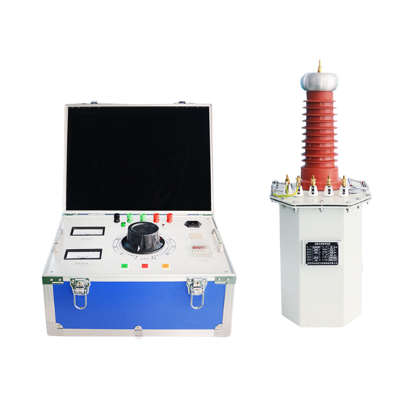
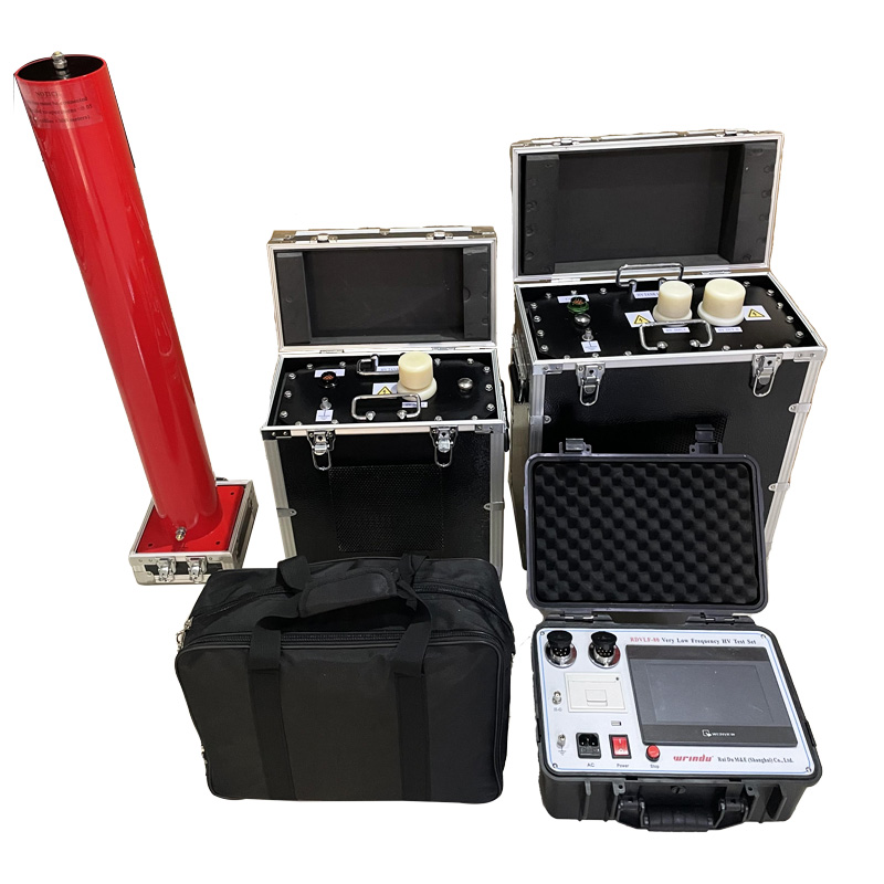
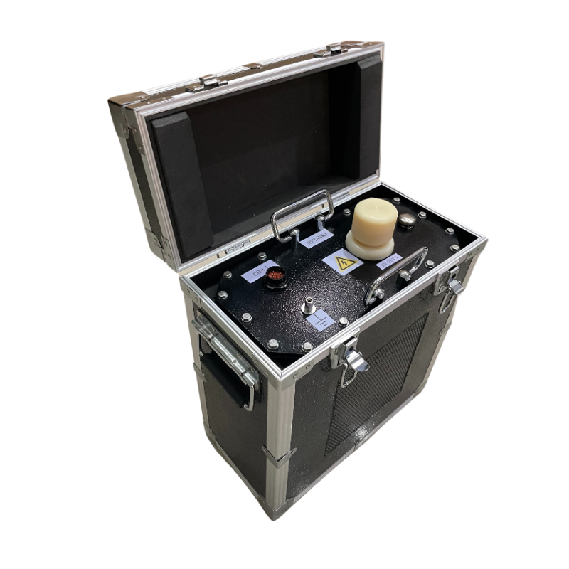
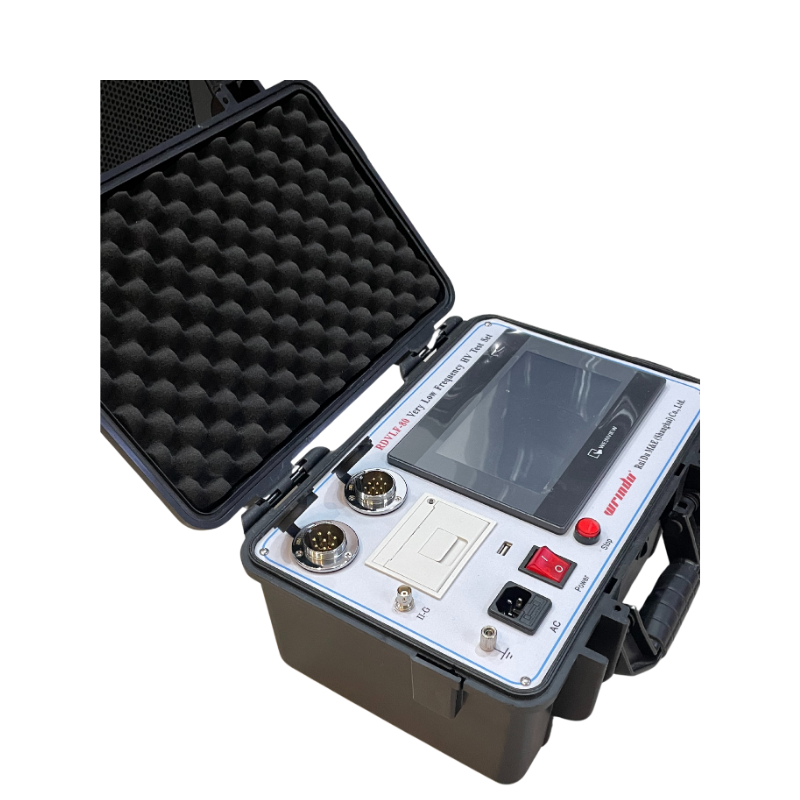
Our VLF Hipot Tester redefines ultra-low frequency signal generation with a fully electronic design that's compact and energy-efficient. It automates voltage adjustments, measurements, and safety protocols, while a manual override option enhances flexibility. The large, intuitive LCD display and built-in thermal printer make on-site reporting a breeze, all without the bulk and high power consumption of traditional systems.
Description
Nowdays mechanical methods are adopted at home and abroad for modulation and demodulation to generate ultra-low frequency signals. Therefore, the sine wave waveform is not standard, the measurement error is large, the high-voltage part has spark discharge, and the equipment is bulky. Moreover, the second and fourth quadrants of sine wave also need high-power high-voltage resistors for discharge shaping, so the overall power consumption of the equipment is large.
This Very Low Frequency VLF Hipot Tester overcomes these shortcomings, combines the advanced technology of modern digital frequency conversion and adopts microcomputer control to realize the complete automation of step-up, step-down, measurement and protection. And manual intervention can be performed during the automatic boosting process. Because it is fully electronic, it has small volume, light weight, large screen liquid crystal display, clear and intuitive. The instrument is equipped with a thermal printer and can print test reports on the test site.
Features
1. Data of current and voltage can be directly sampled at high voltage side, so the data is real and accurate.
2. Over-voltage protection: If the output exceeds the set limit of voltage, the instrument will shut-down to protect itself, the actuation time is less than 20ms.
3. Over-current protection: it is high-low voltage dual protection in the design, the accurate shut-down protection can be made according to the set value at high voltage side; If the current on low voltage side exceeds the rated current, the instrument will take shut-down protection, the actuation time are both less than 20ms.
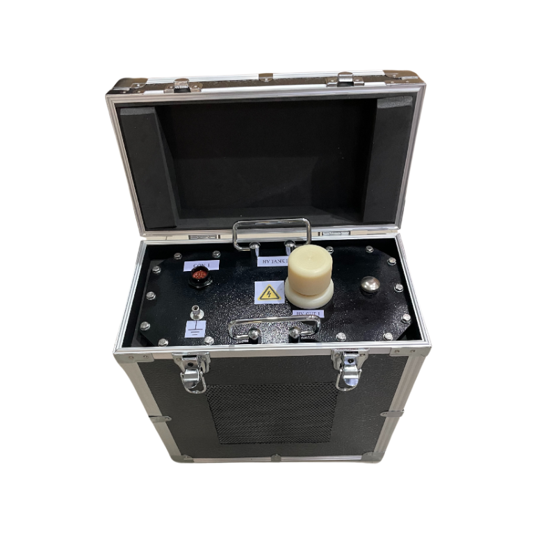
4. High-pressure output resistance design in the booster, so don't need another outside protective resistance.
5. The adoption of high voltage and low voltage closed loop feedback control circuit, so the output is no let up effect.
Specification
1. Rated output voltage and load capacity
Rated output voltage | Load capacity at different frequencies | Booster configuration |
30kV (peak value) | 0.1Hz, ≤1.0µF | Using the No. I booster alone |
0.05Hz, ≤2.0µF | ||
0.02Hz, ≤5.0µF | ||
0.01Hz, ≤10.0µF | ||
50kV (peak value) | 0.1Hz, ≤0.4µF | Using the No. Ⅱ booster alone |
0.05Hz, ≤0.8µF | ||
0.02Hz, ≤2.0µF | ||
0.01Hz, ≤4.0µF | ||
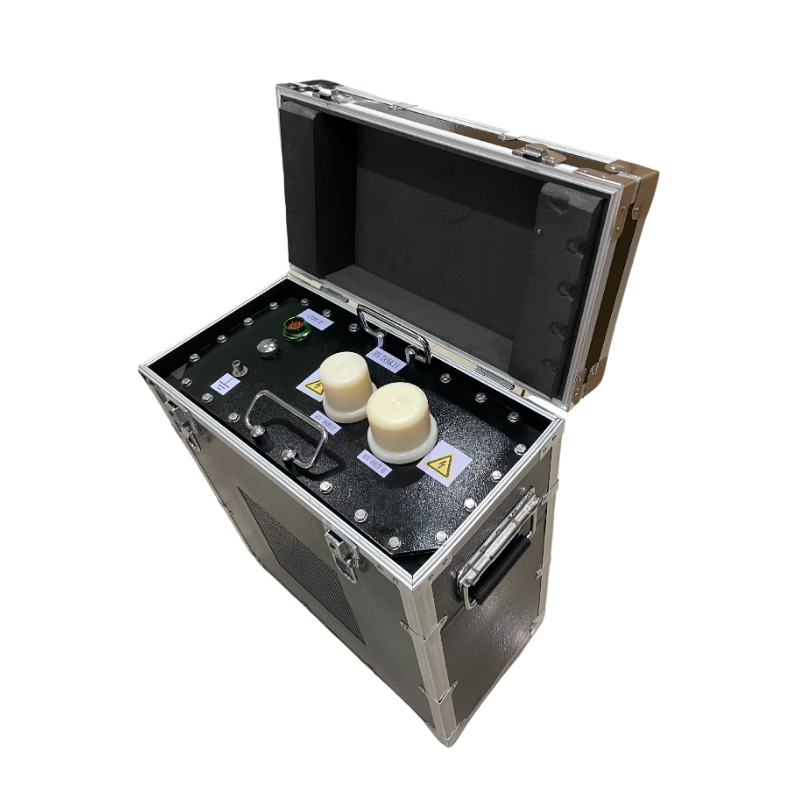
80kV (peak value) | 0.1Hz, ≤0.35µF | Using booster I and booster II in series |
0.05Hz, ≤0.7µF | ||
0.02Hz, ≤1.75µF | ||
0.01Hz, ≤3.5µF |
2. Measurement accuracy: ± (3%fs+0.5kV)
3. Voltage wave form distortion: ≤ 5%
4. Use condition: temperature -10℃ ~ +40℃; humidity ≤ 85%RH
5. Power supply fuse: 25A
6. Power supply: AC 220V ±5%, 50±0.1Hz